What is a schematic, anyway?
A schematic is an electrical representation of an entire circuit, which basically means you stare at it so you can understand what’s going on in a circuit. Each component on a PCB (a microcontroller unit, sensor, LED, capacitor, resistor) has its own symbol that is a electrical representation of that specific part. So a bunch of symbols put together is a schematic.
Importing symbols
KiCAD comes with a boatload of symbols already, but the ones you’re going to use probably aren’t on there. This is why companies and awesome people on the internet make their own symbols and open-source them so people like us can build epic stuff. Here’s how to import symbols.
In KiCAD’s main window, go to Preferences → Manage Symbol Libraries, click the file icon, and point it at whatever you downloaded off the component list back in Step 2. Do the same for your microcontroller.
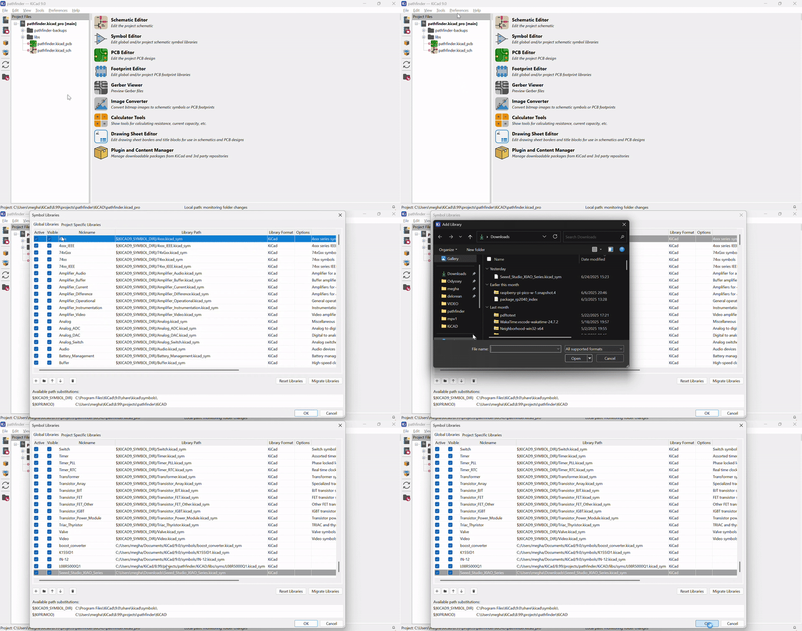
Once a symbol’s imported, hit A on your keyboard to place it, along with any of KiCAD’s built-in default parts (resistors, buttons, whatever else you need).
BAM! You’re done placing symbols. Now, we’ve got to wire it all up and it’ll be a schematic.
What do I wire?
Open your component’s datasheet. A datasheet is just a massive PDF that has everything anyone could possibly want to know about that electronic part. Scroll to the table of contents and CTRL-F the word “pin”. We’re looking for the pinout or pin description table, which tells you what every single pin does and where it needs to connect (a pin is just a connection point for components). This table and the sample circuit will be your best friend.
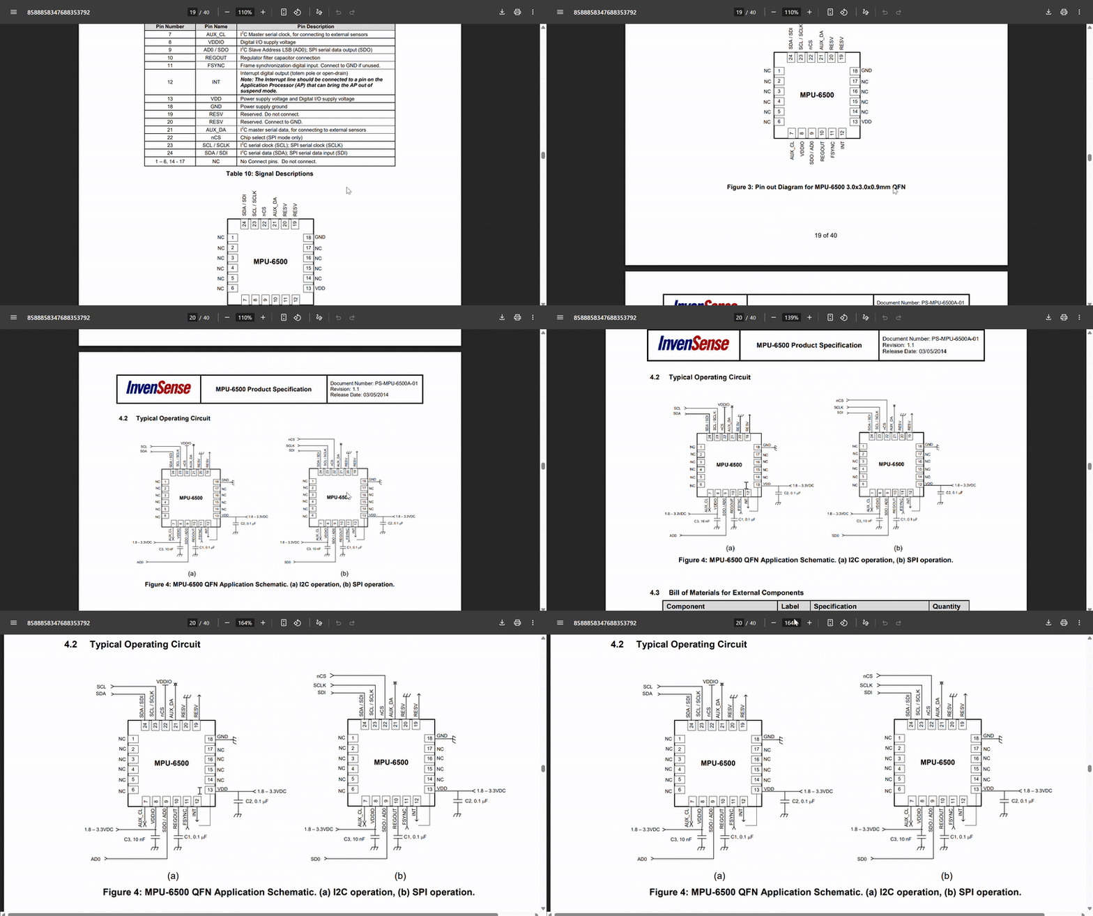
While you’re in there, keep an eye out for two more things:
- A sample / typical application circuit , some datasheets just hand you the whole reference schematic, capacitors and all. If yours has one, copy it almost exactly.
- Whichever communication protocol pins show up. SDA/SCL means I2C. MISO/MOSI/SCK/CS means SPI.
There’s 2 main communication protocols we care about: SPI and I2C (pronounced eye-squared-see). SPI is older, uses more pins, and faster. It generally has 4 pins, MISO (Master In, Slave Out), MOSI (Master Out, Slave In), SCK (serial clock), and CS (chip select). I2C’s pins are SDA and SCL. SDA is serial data (handles data transfer between components), and SCL is serial clock (handles timing of information).
Wiring
You could wire everything with the W key and have a mess of criss-crossing lines, but global labels are way cleaner. WIth CTRL+H, place a label, give it a name, then place a second label with the exact same name (case sensitive) on whatever pin you want it connected to. Same name = same net, no matter how far apart they sit on the page.
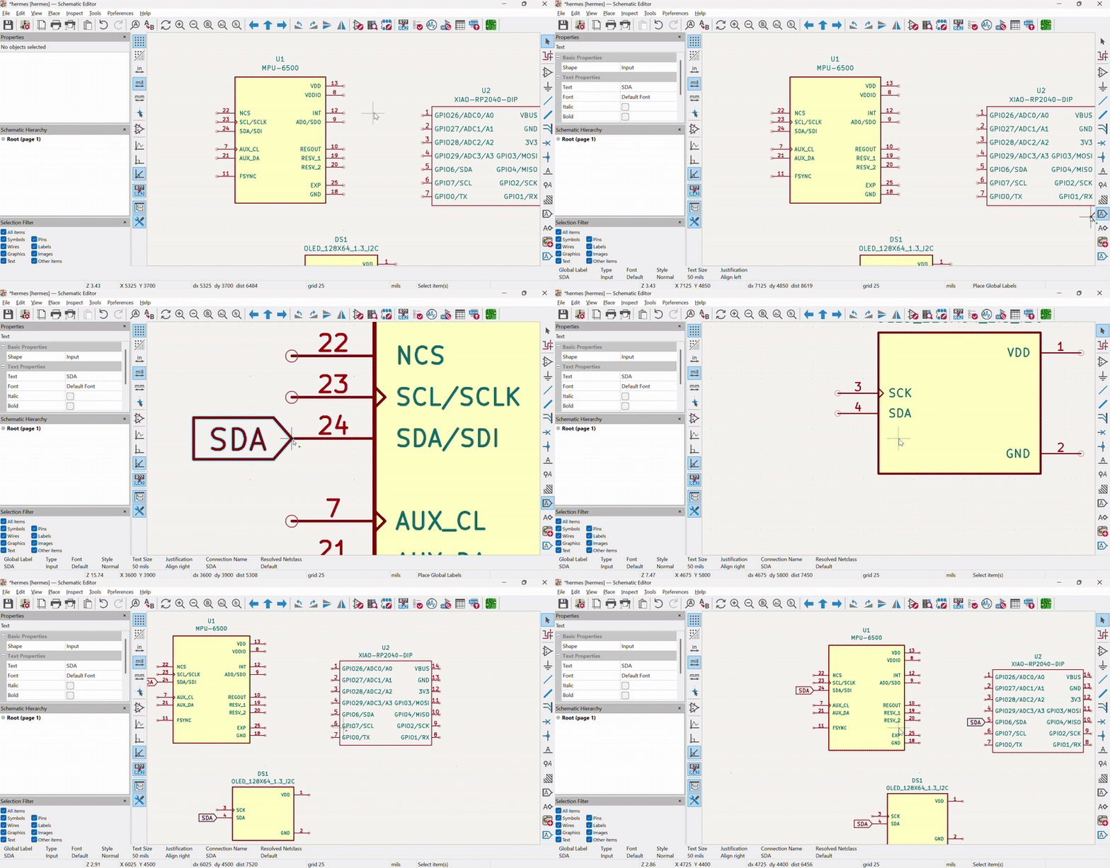
If you’re using I2C (recommended, it’s way easier), every I2C part shares just two pins: SDA (serial data) and SCL (serial clock). Make one global label called SDA and one called SCL, and connect every symbol’s SDA pin to the SDA label and every SCL pin to the SCL label. That’s the whole bus, no matter how many parts you add. Now all your components can talk to each other
You have to connect a 4.7k resistor from SDA up to your voltage rail, and another from SCL up to your voltage rail. These are pull-up resistors. I2C is open-drain, meaning parts can only pull the line low, never actively push it high, without the pull-ups, your data just floats and comes out as garbage.
If your part’s SPI instead, you’ve got four pins to wire: MOSI, MISO, SCK, and a CS (chip select) line per device. More pins, but no pull-ups needed, and it’s usually faster.
Your power pins are pretty important too. Connect power (check whether your part wants 5V or 3.3V , they are not interchangeable) and connect ground. If your datasheet calls for capacitors near a specific pin, make sure you remember that for the next step: they need to sit physically close to the part once you start designing.
Assigning footprints
Once all your pins on all your symbols are connected to somewhere, click the “Assign Footprints” icon and match every symbol to the footprint you downloaded. The schematic just has electrical representations of all the components, footprints are what will actually appear on your board.
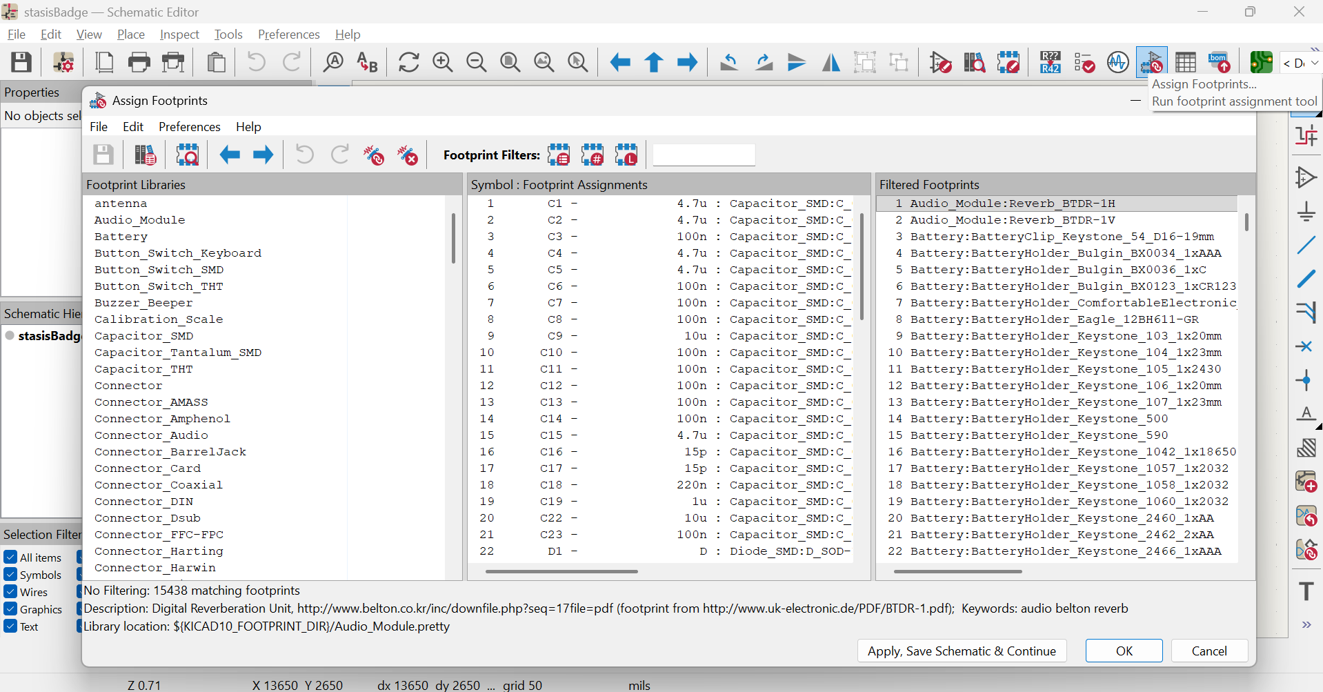
Once you’re done with your schematic, post a screenshot in #runtime. Congrats on your brand new schematic!